

In the second part of this lab, we’ll set up the Site Firewalls. Each will have 2 WAN connections to different ISPs. Then we’ll set up four IPsec tunnels and BGP routing. This setup will guarantee a full redundant connection between these sites. Each site will have one ISP down at a time tolerance.
To check the first part of these lab:
This is our lab topology:

First, install and set up two OPNsense VMs for Site A and Site B.
To check the installation of OPNsense in Proxmox:
Site A Network Interfaces:
| Interface | Identifier | IP Address |
| ISP1 | wan | 10.16.1.1/30 |
| ISP2 | opt1 | 10.16.2.1/30 |
| LAN | lan | 172.16.32.1/24 |
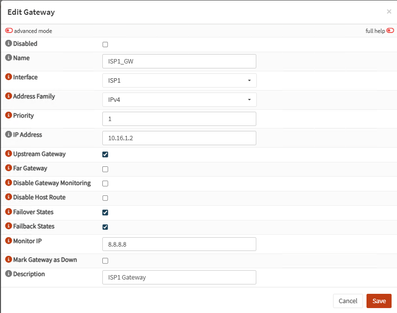
Site A Gateways
| Name | Interface | Priority | IP Address | Monitor IP |
| ISP1_GW | ISP1 | 1 (upstream) | 10.16.1.2 | 8.8.8.8 |
| ISP2_GW | ISP2 | 2 (upstream) | 10.16.2.2 | 8.8.4.4 |
Note: On each gateway select Failover States and Failback States:
Site A General Settings:
Usually your gateways monitoring IPs are your public DNS servers. Make sure to match each DNS with its corresponding gateway:
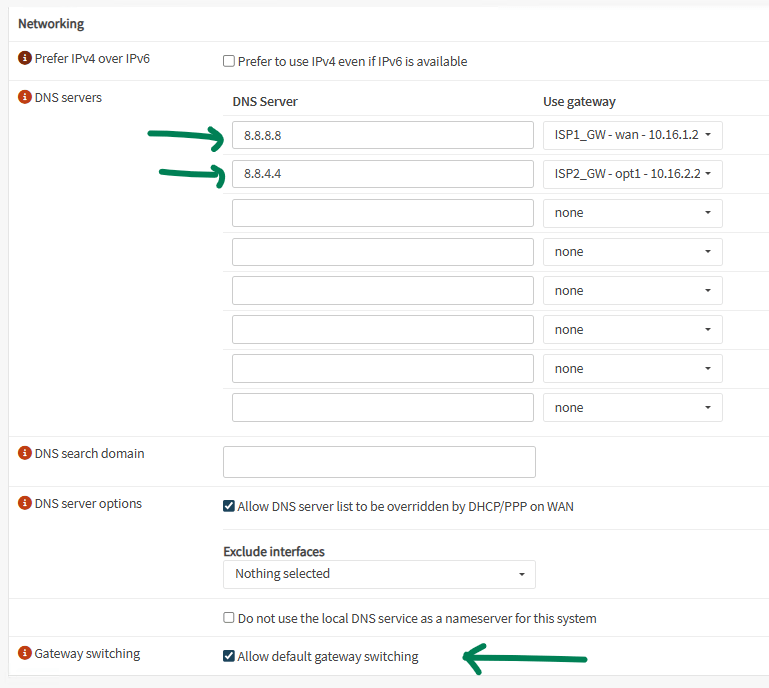
Also select Allow default gateway switching
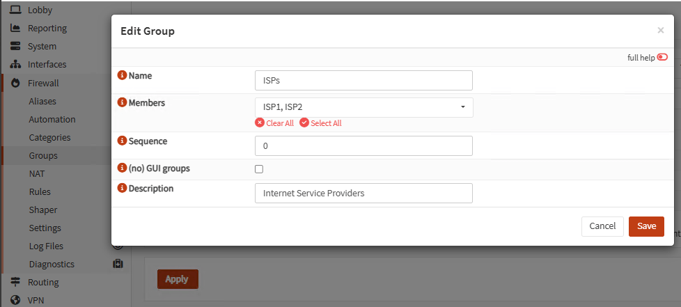
Site A Firewall Rules
Go to Firewall, Groups and create a group for your ISPs interfaces:
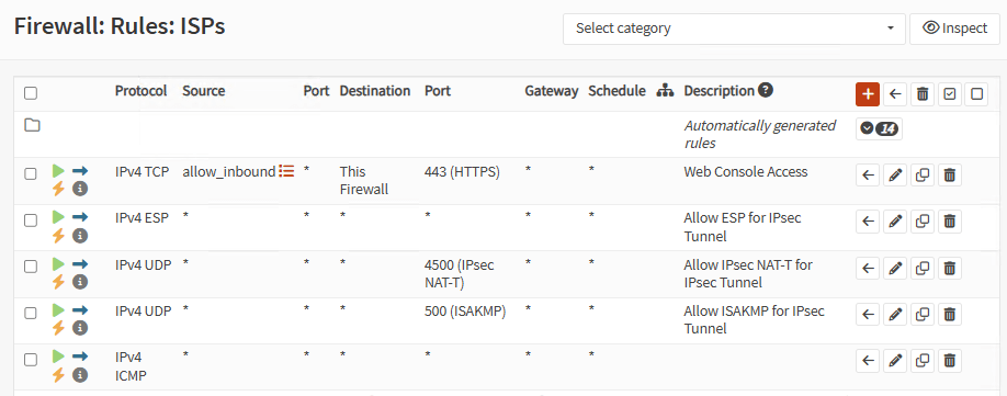
Go to Firewall, Rules, <group_name> and create the next rules:
| Protocol | Source | Port | Destination | Port |
| IPv4 ESP | * | * | * | * |
| IPv4 UDP | * | * | * | 4500 (IPsec NAT-T) |
| IPv4 UDP | * | * | * | 500 (ISAKMP) |
Optionally, create a couple of rules to allow web console access and ping for inbound connections coming to ISP interfaces:
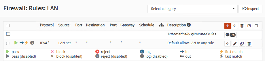
Go to Firewall, Rules, LAN and allow all outbound from LAN:
Site B Network Interfaces:
| Interface | Identifier | IP Address |
| ISP1 | wan | 10.18.1.1/30 |
| ISP2 | opt1 | 10.18.2.1/30 |
| LAN | lan | 172.18.32.1/24 |
Site B Gateways
| Name | Interface | Priority | IP Address | Monitor IP |
| ISP2_GW | ISP2 | 1 (upstream) | 10.18.2.2 | 8.8.8.8 |
| ISP1_GW | ISP1 | 2 (upstream) | 10.18.1.2 | 8.8.4.4 |
Note: On each gateway select Failover States and Failback States:
Site B General Settings:
Same as Site A
Site B Firewall Rules
Same as Site A
Now let’s create the tunnels.
Site A Firewall
Go to VPN, IPsec, Tunnel Settings. Create four Phase1 starting with ISP1 to ISP1.
General Information:

Note: It’s important to type a short and meaningful description for the Phase1. This is because the new firewall interface will be named like that.
Phase1 proposal:
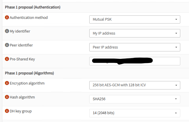
Note: For testing purposes, use the same Pre-Shared Key on all Phases1
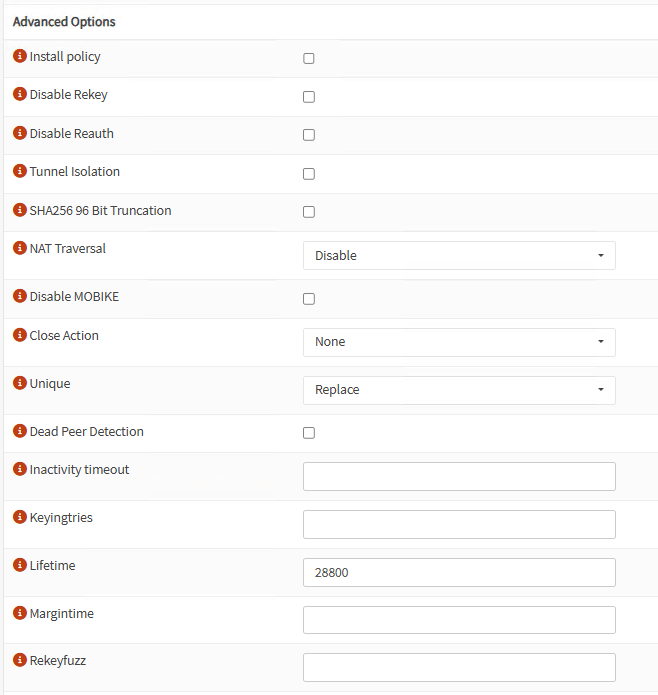
Advanced Options:
Repeat three more Phases 1 for:
- ISP1 to ISP2
- ISP2 to ISP1
- ISP2 to ISP2
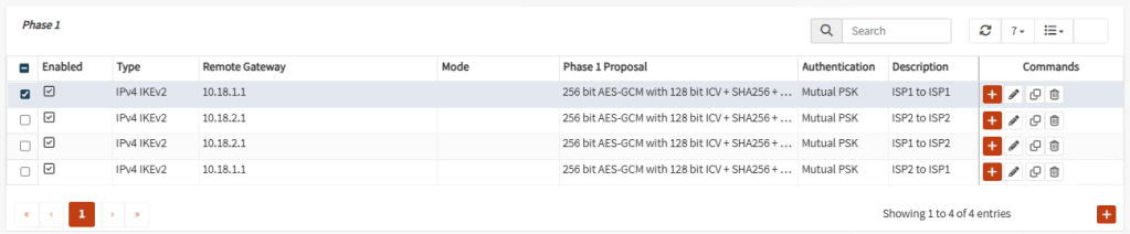
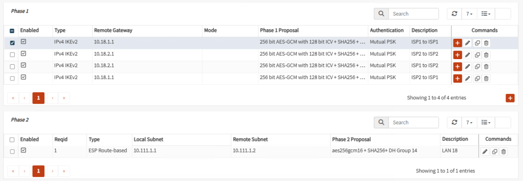
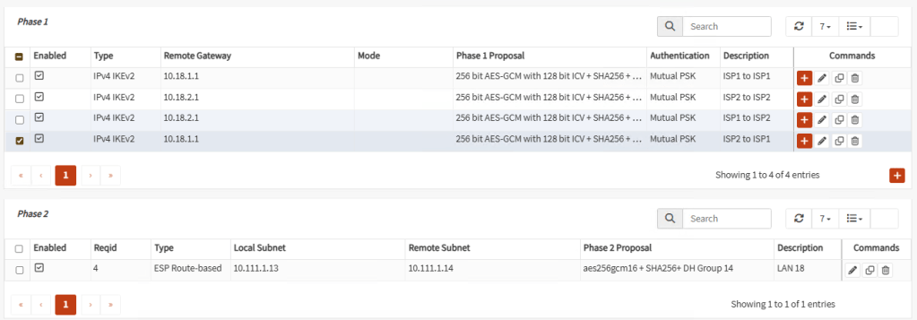
Your Phase 1 tunnels should look like this:
Now, let’s create Phase 2 on each Phase 1. Select the first Phase 1, ISP1 to ISP1 and create a Phase 2:
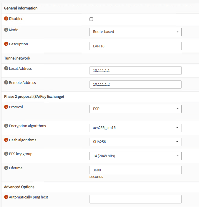
Note: BGP only works with Route Based tunnels, so be sure to select the mode correctly.
Note: For Local and Remote Address you can select any private not used couple of /30 IP Addresses. Remember to switch the values on the Phase2 of Site B for the corresponding tunnel.
Create the corresponding Phase 2 for the other three Phases 1. At the end, your tunnels should look similar like these:
Tunnel 1
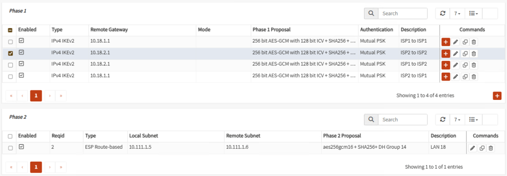
Tunnel 2
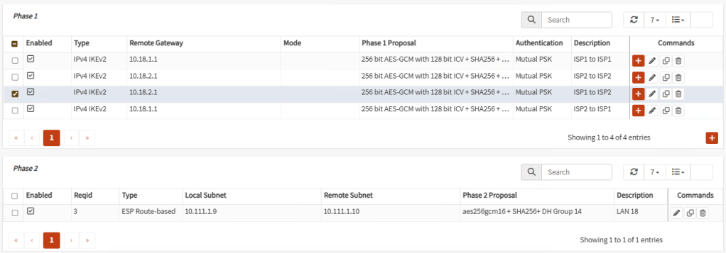
Tunnel 3
Tunnel 4
Note: At the end, don’t forget to Enable IPsec with the check mark at the button.
Site A Firewall Rules
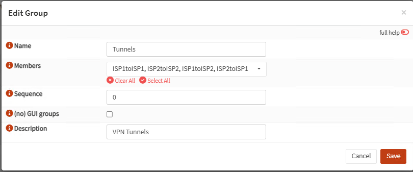
Same as ISP interfaces, go to Firewall, Groups and create a new group for the four new interfaces:
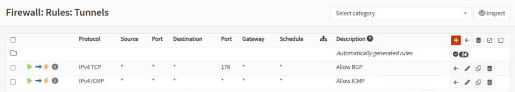
Go to Firewall, Rules, <tunnels_group_name> and add a rule to allow TCP port 179 and optionally ping:
Go to Firewall, Rules, IPsec and add the same rules as in tunnels and also a rule to allow anything to LAN network:
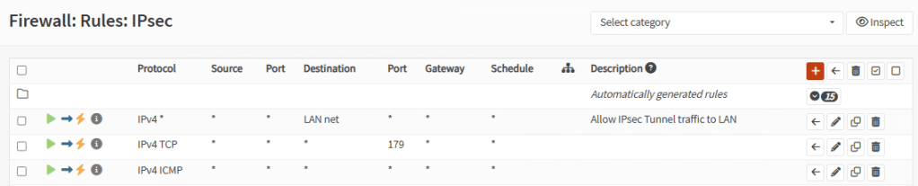
Note: In production scenarios, you want to review all access to LAN on tunnels.
Site B Firewall
Repeat the same configuration of Site A on Site B switching the IP Addresses in Phase 1 and Phase 2.
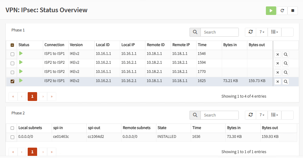
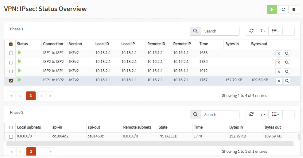
Check Tunnels
At this point, your tunnels should be up and running. You can check them on VPN, IPsec, Status Overview:
Firewall A:
Firewall B:
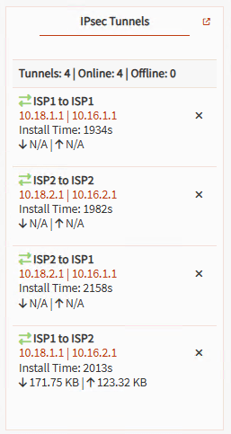
Note: You can also add the widget on the Dashboard:
Now, let’s set up routing. On the each firewall, go to System, Firmware, Plugins and install os-frr plugin.
Note: You need to update your firewall.
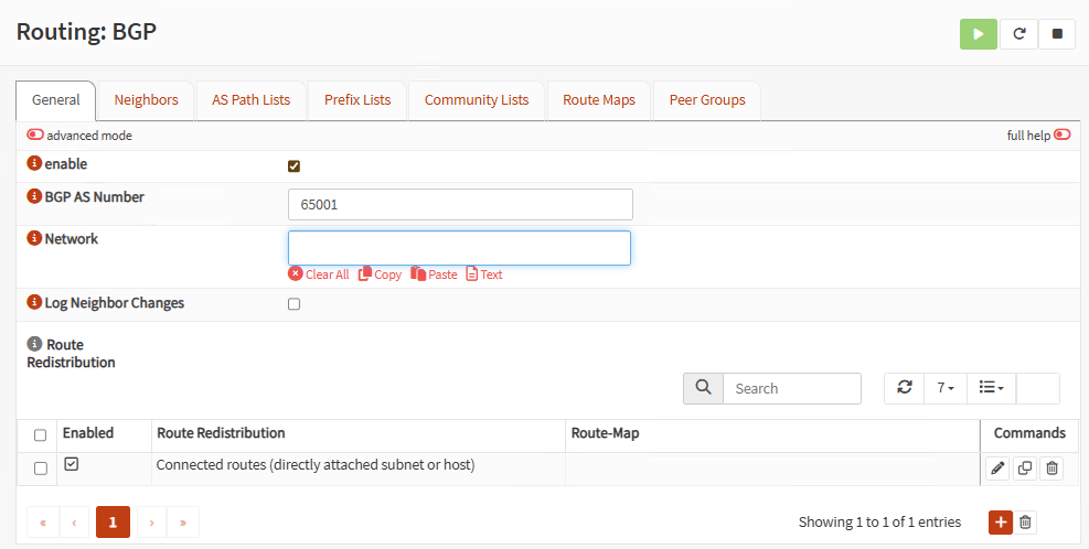
Go to Routing, BGP:
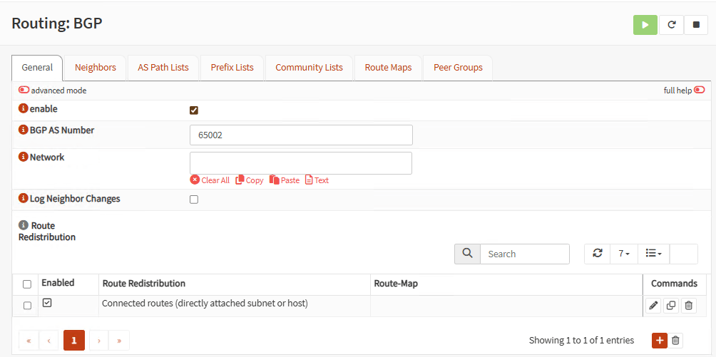
Firewall A:
On the General tab, click enable, use a BGP AS Number above of 65000 like 65001, and add Connected routes on Route Redistribution:
Go to Prefix Lists tab and add your local LAN:
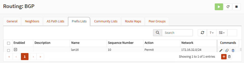
Note: If you have more LANs, you can add them here.
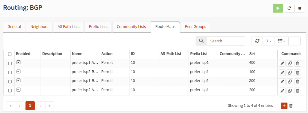
Go to Route Maps tap and add four route maps, one for each tunnel, associating your prefix list networks. You can use the same ID, but use different set numbers for each route map. Higher numbers, have higher precedence.
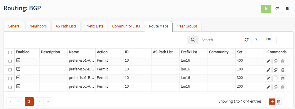
Note: Prefix Lists and Route Maps are optional. But, in production environments, it is important to show which tunnels have higher precedence over others. This will manage fail-over and fail-back of the tunnels when ISPs go up and down.
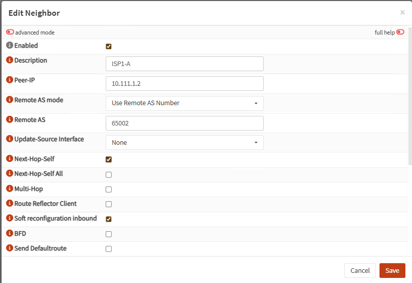
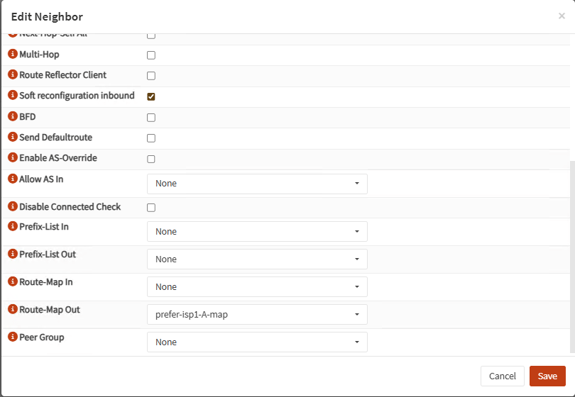
Now go to Neighbors and add the four remote neighbors on the other firewall. Peer-IP is the remote Phase 2 IP in the corresponding tunnel. Use the neighbor Remote AS and associate the right Route Map in Remote Map Out:
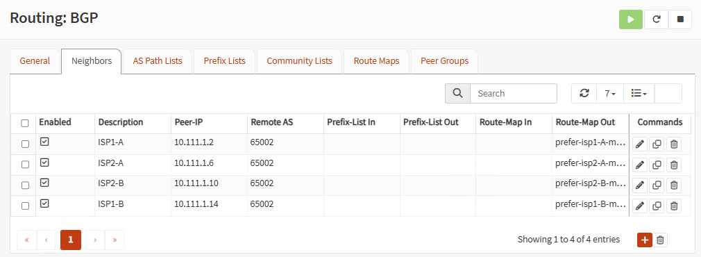
On each neighbor, check Next-Hop-Self and Soft reconfiguration inbound:
Finally, go to General and enable everything:

Restart the firewall.
Firewall B:
Same as Firewall A. Use a different BGP AS Number like 65002 and switch IP address of neighbors:


On General, enable everything and restart firewall B as well.
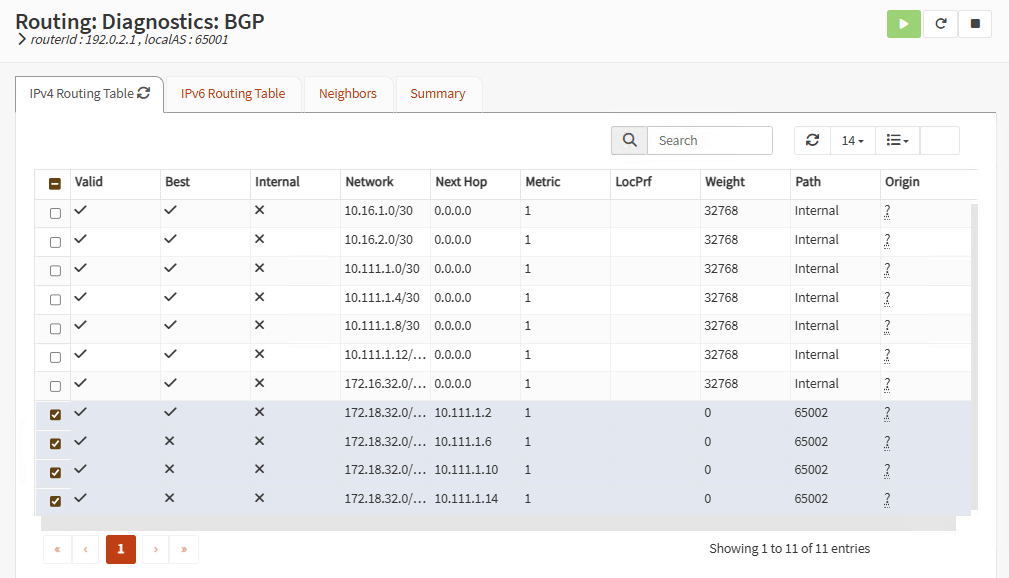
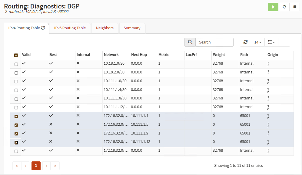
Routing should be working right now. On each firewall go to Routing, Diagnostics, BGP and you should see the exchanged routes with each neighbor:
Firewall A:
Firewall B:
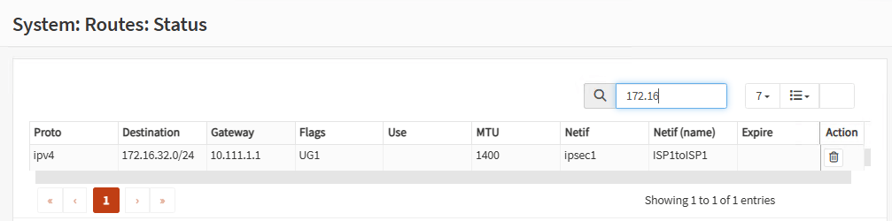
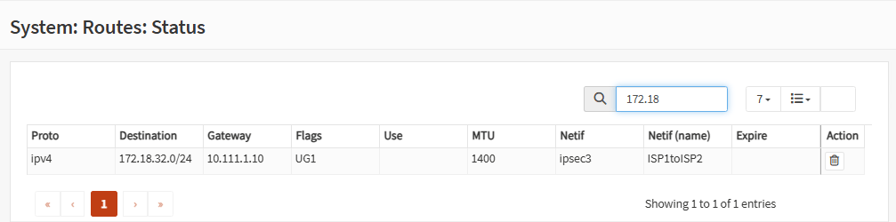
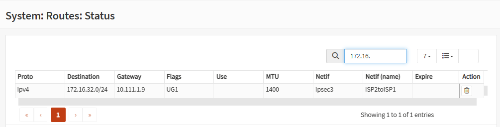
You can also go to System, Routes, Status and you should see the route to the remote LAN and the active tunnel interface providing this route:
Firewall A:
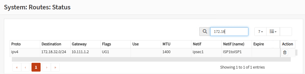
Firewall B:
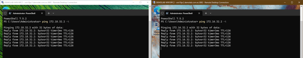
Now it’s time to check everything. Go to the workstation on Site A and ping workstation on Site B. Go to Site B and ping Site A as well. You should see pings are OK. Both sites are communicating over a Tunnel between ISP1 and ISP1 (route map higher precedence). Leave the pings open.
Now you can play around. Go to one of your WAN routers and disconnect one ISP on Site A Firewall. See how the tunnels switch between your firewalls. Pings disconnect a few seconds but they connect again. The BGP protocol is doing its work.
Go to the other WAN router and disconnect one ISP on Site B Firewall. The tunnels switch again to the whatever path is available:
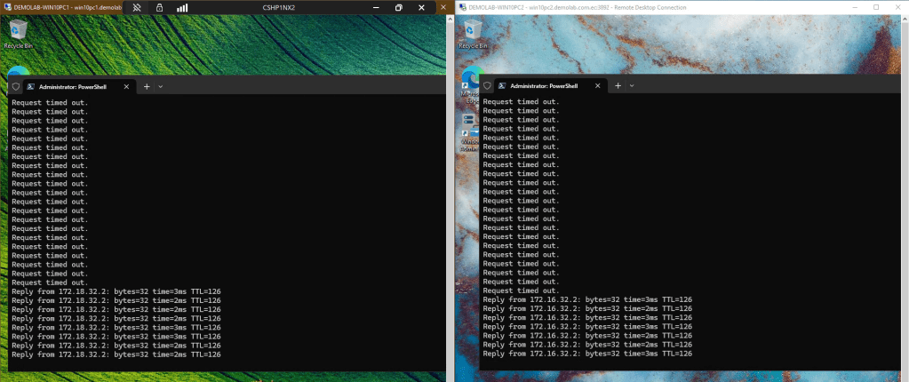
On each firewall, go to System, Routes, Status and you should see which tunnel is providing the route:
Firewall A:
Firewall B:
Reconnect the ISPs on your routers one by one. Watch how the tunnels return to the configurations in your route maps.
That’s it. This is how you set up two OPNsense firewalls to have redundancy with two ISPs on each site. You can set up the same with other brands of firewalls. The theory is the same. You should check the documentation for the other brands. This will help you set up Route Based IPsec VPN and BGP.
Don’t forget to leave your comments and suggestions.
Have Fun!

Leave a reply to Configure Redundant OPNsense IPsec Tunnels with BGP Between Two Sites (Part 1) – RacerX Steppenwolf Cancel reply